Autodesk FormIt: Dynamo’s Overlapping Planes Building Script
During our last FormIt webinar we shared how to transfer 3D terrain into a model through:
- Use of the location finder,
- A 2D plan to overlay a site plan onto the 3D terrain,
- Dynamo to quickly create a building form using multiple 2D planes,
- Dynamo to convert walls into a store front system,
- And finally placing the building into the 3D terrain model.
Watch the on-demand webinar “Using FormIt to Create 3D Terrain, Site, and Building Layouts” here* >
These follow-up blog posts provide more details around the process we outlined. Today’s post covers Dynamo’s “Overlapping Planes Building” tool. So boot up FormIt and get ready to create!
To get started, you will need to download the “Overlapping Planes Building” Dynamo script >
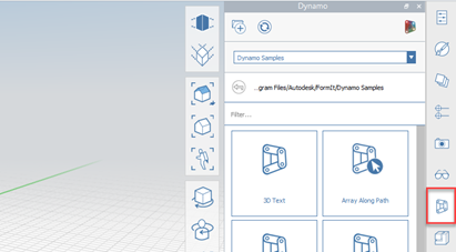
Be sure to save the script into a Dynamo folder to easily locate it within FormIt. Once you have the script in your desired location, click on the Dynamo icon in FormIt.
We will need to direct FormIt to the Dynamo file structure, so click the “link Dynamo directory” button in the top left of the Dynamo window (indicated by the red arrow). A new window will open, and again, you will want to click the “+” sign to add your Dynamo folder to the directory (indicated by the green arrow). Click on the Dynamo folder you just created and then hit “select folder.” Then click “Ok” to finalize the link.
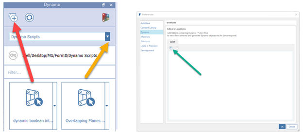
You should now have the “Overlapping Planes Building” dynamo script available to you. You will have Dynamo scripts already available to use that are native to FormIt, so be sure to use the drop-down menu to select your local folder (indicated by the above yellow arrow).
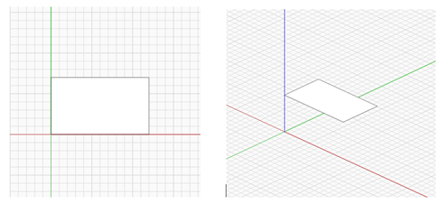
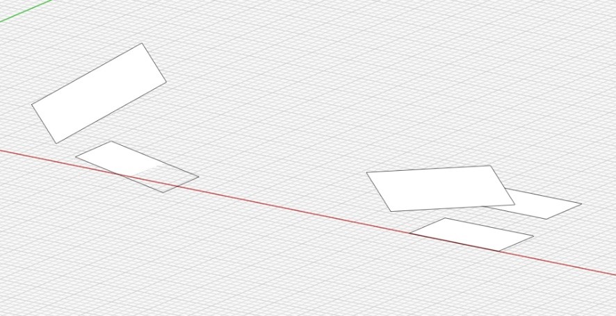
Now, let’s get into drawing a new building using 2D planes. First, jump into a plan view (VT for the shortcut), and draw a rectangle of any dimension. Personally, I like to use an orthographic view, but a perspective will also work. Then, go into an elevation view (vf, vr, vl or vb), select the rectangle and pull it off the ground however high you would like.
Repeat the process for a second rectangle but let us rotate the second rectangle a little bit, and then let’s make sure the rectangles overlap a bit. Be sure to go into an elevation view and pull the second rectangle off the ground. Give it a different height than the first rectangle.
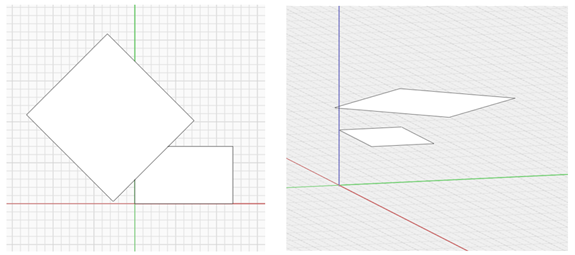
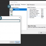
Select both rectangles and put them on their own layer. We will be able to use this a little bit later in the process. These two planes will essentially be the roof footprint for our new building.
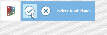
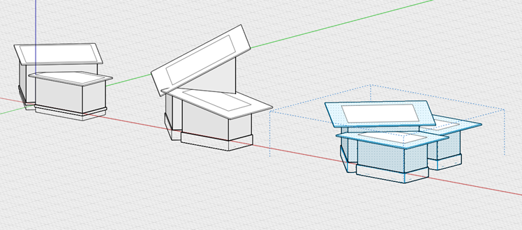
With our planes now on their own layer, let’s use the Dynamo script. Simply click on the script, and it will ask you to select the planes you would like to use. Please note that you can draw as many planes as you would like. You are not limited to one or two. In our case select both planes. You can use a selection box around both planes or select them individually. Once both are selected hit the check box.
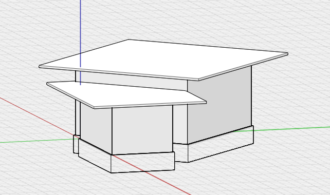
You now have a building complete with roof, walls, floors, and foundation walls. Note that these items have also been placed within their own groups. Turn off your roof planes layer to see the building without the planes.
Let’s go in and start messing around with some of the settings. Select your building and right-click edit group (e). Once you have done this, you will see in the group properties window all the settings that are a part of the script. Let us go in and change the roof overhang to 2ft, and the foundation walls height to 1ft and click “run”. Notice how the building changes.
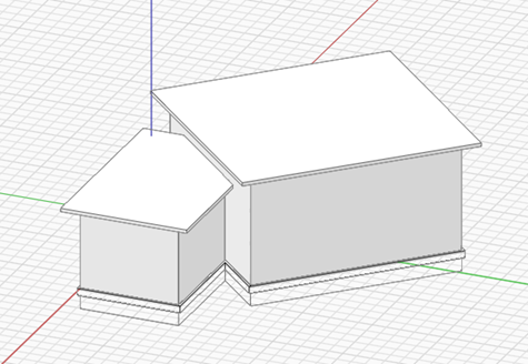
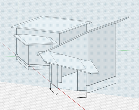
Feel free to play around with these settings to see how they can change your buildings. Select your building and put it on a new layer, turn it off and then turn your roof planes layer on. Make a couple copies of your roof planes and spread them out so we can edit them. Rotate the planes on one set, and then add an additional plane to the other.
Run the Dynamo graph and check out the results.
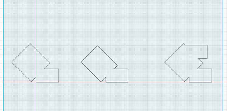
Finally, we are going to cut a quick section through one of the buildings.
Notice how the intersecting shapes are automatically cut out and turned into different spaces! We can check it out in a plan view too.
Thank you for reading this blog, and I hope we have been able to show you how quick and easily you can develop intricate building shapes using FormIt and Dynamo. Check back soon for additional posts on other custom Dynamo graphs; “Multi-family Building Generator” and an in-depth post on “Project 2D Plan onto 3D Terrain”.

Will Campbell is a Building Design Technology Specialist at MG AEC Technology Partners. He is OHSA certified and a licensed architect in the state of Colorado.

*please note: this webinar is gated and requires registration to access.